This is the story of a DSP modelling mistake. It arises when a feed-forward compressor design is moved into a feedback topology without adjusting the gain computer. The ratio then no longer sets the slope of the transfer curve, so the knob stops meaning what its label says. Here is how it works.
Throughout the article, everything is in dB and in steady state. The compressor is set with a hard knee and above the threshold, the compressor reduces gain. Below it, the output equals the input and the gain reduction is zero.
Feed-forward topology
In a feed-forward VCA compressor, the dB output \(y\) can be expressed as a function of the dB input \(x\), the dB threshold \(T\), and the compression ratio \(R\):
when the input level is greater than or equal to the threshold. The gain reduction is a non-positive function \(g\) which represents the difference between the output and the input:
We can derive its expression from the previous equation:
The slope of the transfer curve is the derivative of the output \(y\) with respect to the input \(x\):
This means that a move in the input produces a move in the output equal to that move divided by \(R\). We can see that:
A very large compression ratio is therefore equivalent to a brickwall limiter, i.e. the output is pushed down towards the threshold.
Feedback topology with unadjusted slope
Now let's move to a feedback topology, where the detector sees the output \(y\) instead of the input \(x\). The gain reduction function now depends on \(y\). If we reuse the feed-forward expression unchanged, evaluating it at the output:
then the output must satisfy a circular relationship, because the gain depends on the output, which itself depends on the gain:
We calculate the slope of the transfer curve by differentiating with respect to the input \(x\):
and solving for \(\dfrac{dy}{dx}\) we find:
The ratio a listener actually gets is the reciprocal of this slope, which we can call the apparent ratio:
A setting of \(R = 2\) therefore gives only 1.5:1. If we once again ask what happens when the ratio becomes extremely large:
So raising the ratio to very large values gives gain reduction that behaves like, at most, a 2:1 feed-forward compressor. The ratio has lost its expected meaning as the inverse of the slope of the transfer curve.
Feedback topology with corrected slope
We need the right gain reduction function for the feedback case, one that restores the inverse relationship between the slope and the ratio we had in the feed-forward case. Let's assume the gain reduction function \(f\) is a linear function of the output \(y\), where \(a\) and \(b\) are real numbers:
We then express the output \(y\) as a function of the input \(x\):
The derivative of the output \(y\) with respect to the input \(x\) is then:
Forcing the slope to be the inverse of the ratio gives us an expression for \(a\):
Honouring the constraint that there is no gain reduction when the output is equal to the threshold gives us an expression for \(b\):
So we should choose our gain reduction function as:
As a check, substituting \(a\) and \(b\) back into the expression for \(y\) recovers the feed-forward transfer curve exactly:
What this means
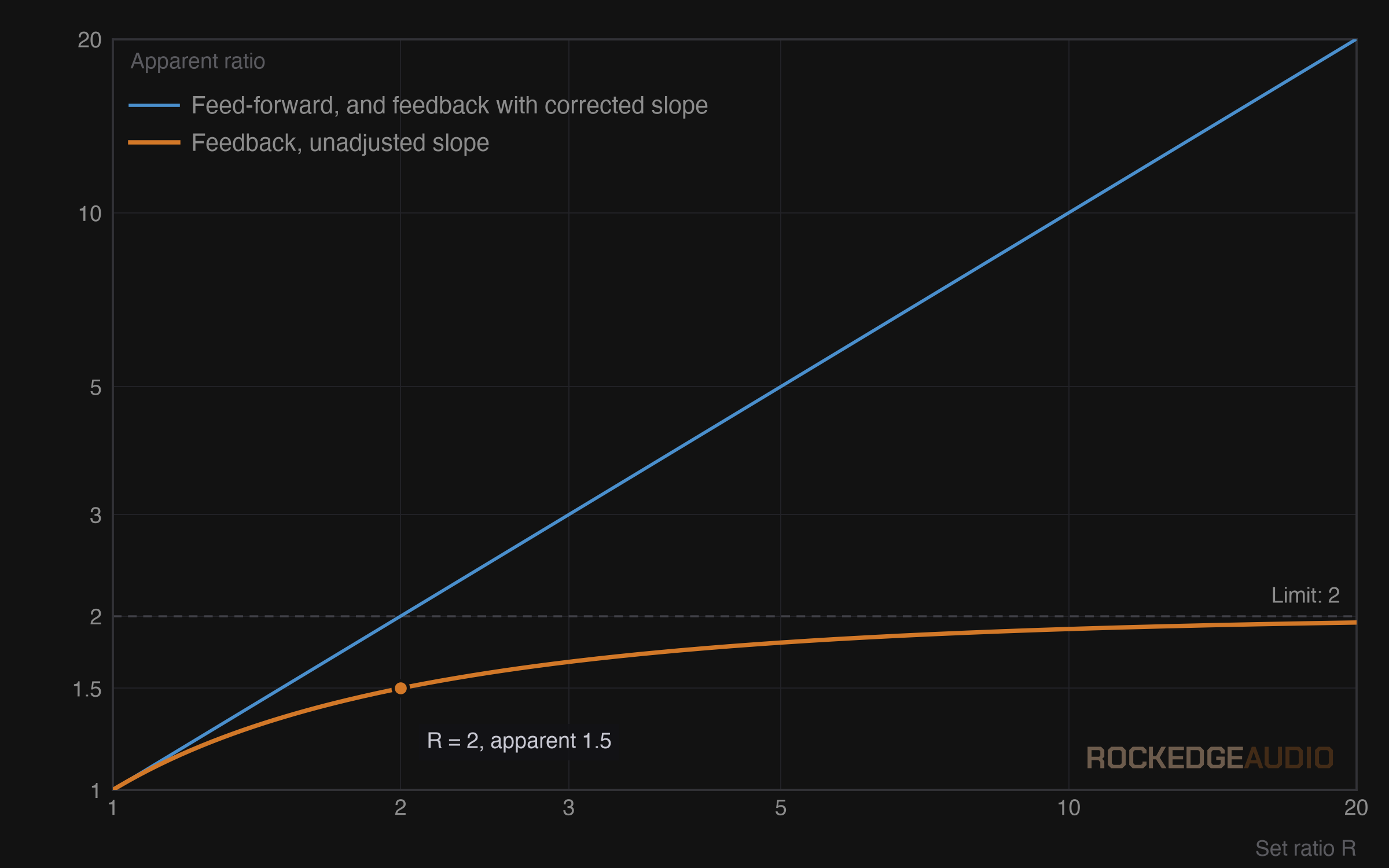
With the corrected slope, the static transfer curve of the feedback topology is identical to the feed-forward one, so the ratio on the knob is the ratio you get.
This does not make the two topologies equivalent. The detector sees a different signal in each, so attack and release behave differently. This in itself can be the topic for another article.
I wanted to share this issue because I encountered it while designing the compressor stage of the RA-CS1 plugin. These findings explain why the topology ended up being feed-forward.